


Set-up
Set the menu set to polygons. Set the shelf to polygons.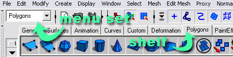
Introduction
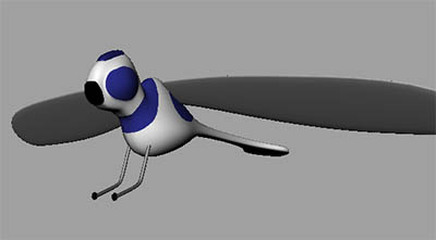
We'll be modeling a dragonfly from polygonal primitives (cubes). This tutorial uses a lot of the extrude tool,Also, as an additional note, to view your model as a wireframe press 4, to view your model shaded press 5.
Setting Up The Camera
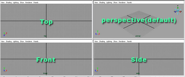
Throughout this tutorial we'll be modeling a 3-dimensional object. Since, when using the default camera you can only see two dimensions at a time, it's best to split the main view port into four views.To do this...
Go to window>saved layouts>four view.
Setting Up The Image Plane
We'll be using an image plane to display our blueprints in Maya. Image planes are connected to cameras. Example: The side camera's image plane would be connected to the side blueprint file.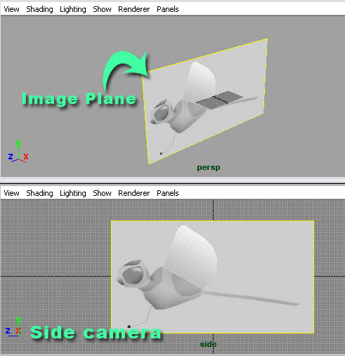 Now let's create the image plane.
Step one - On your side view port, go to view>image plane>import image... Locate the bitmap file that you downloaded as a blueprint on your hard drive.
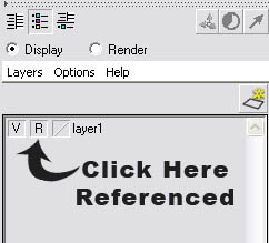
Step two - Now that we have our image plane in Maya, we have to reference it. That means you can't accidentally select it when modeling. Go to display>UI elements>channel box/layer editor.
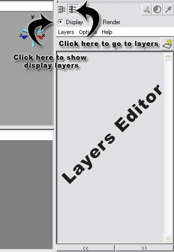 Step three - In the layers editor, go to layer>create empty layer.
Step four - Select the image plane (you may need to click on the green edges).
Step five - Right click on the new layer and go to add selected objects.
Step six - Click the template/reference toggle button two times. When it displays R that means the layer has been referenced.
Modeling
We'll be modeling our toy dragonfly from cubes. To create our first cube, go to create>polygonal primitives>cube.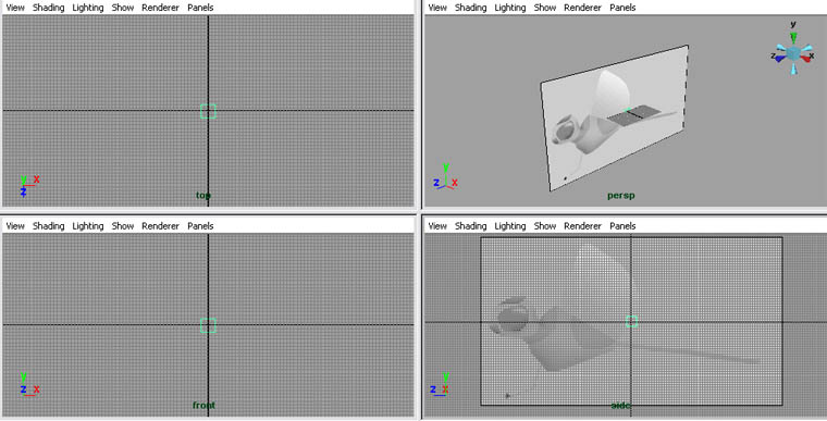 Use the move tool to move it into the position. Use the image below for reference.
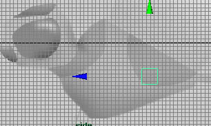 Now press F9 on your keyboard. What this does is put
your cube into vertex mode. This way we can select and move vertices
instead of the entire object. vertices, edges, faces, UVs, etc. are
components. To exit a component mode, press F8.
Now press F9 on your keyboard. What this does is put
your cube into vertex mode. This way we can select and move vertices
instead of the entire object. vertices, edges, faces, UVs, etc. are
components. To exit a component mode, press F8. Now you can edit your vertices. Position the vertices, using the move tool like in the image below. Tip - Select the vertices by making a square over them. That way you select and move both sides.
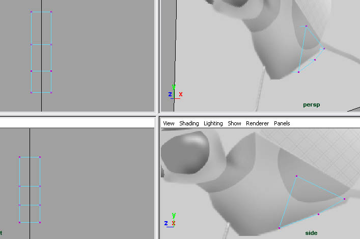 We're going to make an extrusion. To extrude a model, you need to select
faces, another type of component like vertices. To enter face mode,
press F11.
We're going to make an extrusion. To extrude a model, you need to select
faces, another type of component like vertices. To enter face mode,
press F11.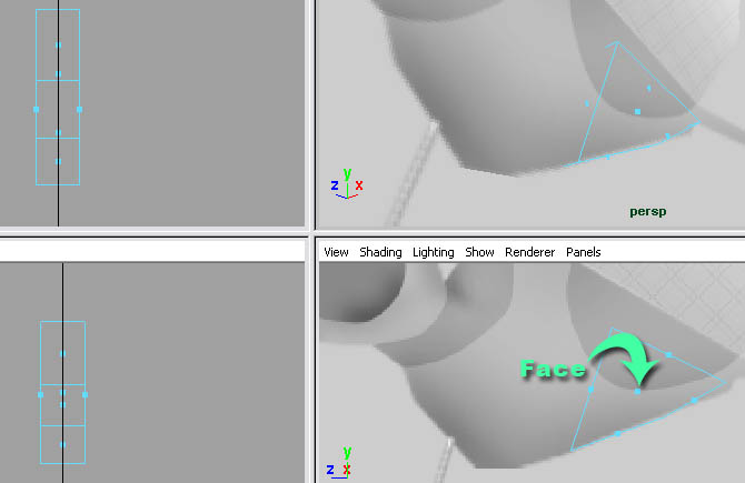 The blue dots in the polygons (squares) are the faces. Every polygon has at least 3 vertices, 1 face, and 3 edges.
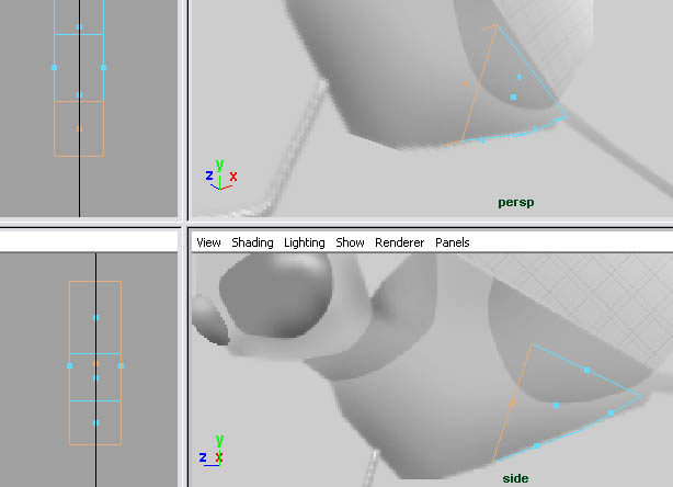
Select the faces on the front of the cube.
 Go to edit mesh>extrude. Use the extrude tool's blue handle to move the faces about halfway up the model.
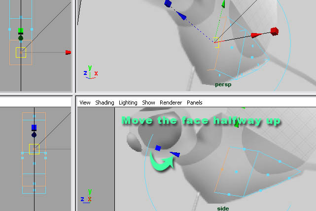 Now we need to make another extrusion. Once again select the faces on
the front and go to edit mesh>extrude, and move them to the base of
the neck.
Now we need to make another extrusion. Once again select the faces on
the front and go to edit mesh>extrude, and move them to the base of
the neck.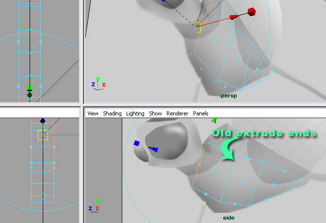 Go back to vertex mode (F9) and move your vertices like in the image below.
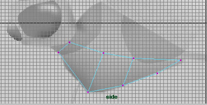 Go to face mode (F11) and select all the faces on the top of the model. I
went to shaded display mode so it would be easier to see.
Go to face mode (F11) and select all the faces on the top of the model. I
went to shaded display mode so it would be easier to see.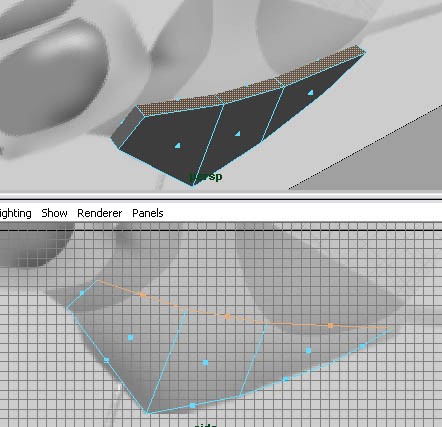 Make another extrusion.
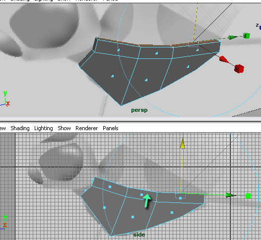 Select the faces that you just extruded and extrude them again.
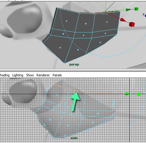 Now go to vertex mode and position the vertices.
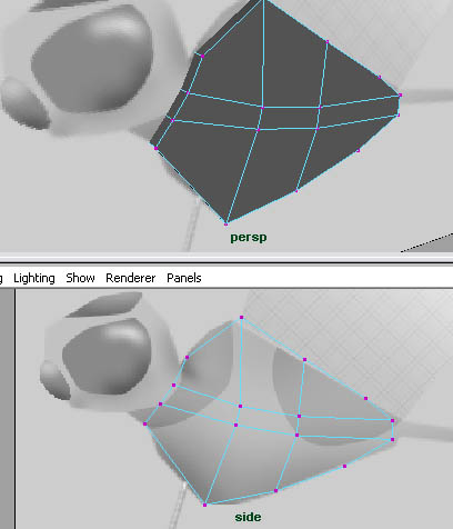 Now that we've got the basic body shape, we need to extrude the head. Go to face mode. Select the faces on the base of the neck.
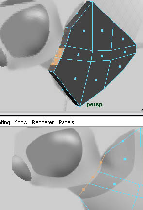 Extrude them up to the back of the head.
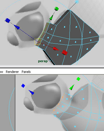 Now make another extrusion to the nose.
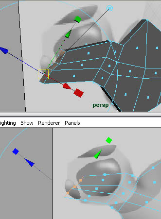 Go to vertex mode and position the vertices.
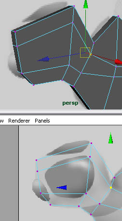 Go back to face mode and select the face on the base of the tail.
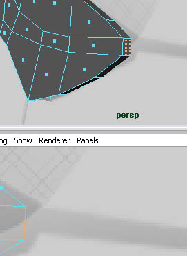 Extrude the face to about 3/4 of the way down the tail.
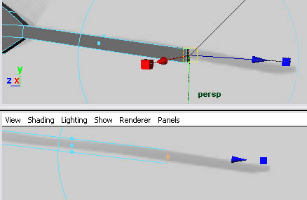 Using the same face, make another extrusion for the rest of the way.
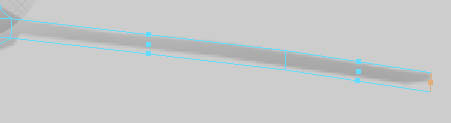
Creating A Smooth Proxy
Most of the time, models will be smoothed when they're finished. Smoothing adds more edges and faces, also smooths out the geometry. To smooth your model, go back to object mode (F8), select the object and go to mesh>smooth.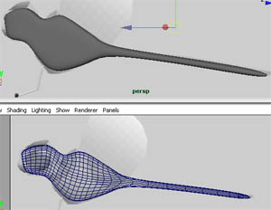 Now that we have more vertices and faces, it will make the model harder
to edit. Also a downside, it's hard to make sure the opposite side of
the model looks the same as the side you're modeling. This is where the
smooth proxy comes in. A smooth proxy lets you have one side low poly
(unsmoothed geometry) and the other side smoothed. The smoothed side
will mirror everything you do on the low poly side. So let's set one up.
Undo smoothing your model (edit>undo or ctrl+z).
Now that we have more vertices and faces, it will make the model harder
to edit. Also a downside, it's hard to make sure the opposite side of
the model looks the same as the side you're modeling. This is where the
smooth proxy comes in. A smooth proxy lets you have one side low poly
(unsmoothed geometry) and the other side smoothed. The smoothed side
will mirror everything you do on the low poly side. So let's set one up.
Undo smoothing your model (edit>undo or ctrl+z).Step one - Select your model.
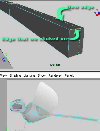
Step two - We're going to need to cut our model in half, but we don't have an edge to cut it on. We're going to use the insert edge loop tool (we'll be using this a lot more in part two ) to add an edge loop all around the model. Then we'll delete the faces on one side of the model.
To access the insert edge loop tool, go to edit mesh>insert edge loop tool. Click on a horizontal edge; it doesn't matter which one, as long as it's along the edge that we need to cut.
 Step three - As you can see, the edge isn't 100%
cutting the model in half. We need to have this accurate or the smooth
proxy won't work. So select the object in object mode and go to
window>attributes editor.
Step three - As you can see, the edge isn't 100%
cutting the model in half. We need to have this accurate or the smooth
proxy won't work. So select the object in object mode and go to
window>attributes editor.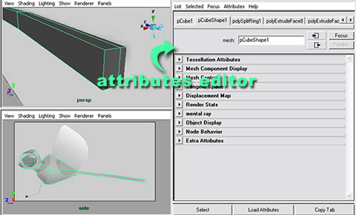 Step four - As you can see, there are a lot of tabs in the attributes editor. The first two tabs are the transform node and the shape node.
These nodes, when connected together, make up your model. The transform
node contains the information like where your model is in the scene,
and the shape node would have information like how many vertices are on
the model, where are these vertices ; also it would have face, UV, edge
etc. information as well. The nodes behind those two nodes are called history nodes.
These nodes are all of your past tools that you've been using on your
model. In other words, you can click on any of the tabs and edit any of
your past tools you used to edit your model. Now, what we need to edit
is the insert edge loop tool. But the history node it creates is called polySplitRing#. Click on that tab.
Step four - As you can see, there are a lot of tabs in the attributes editor. The first two tabs are the transform node and the shape node.
These nodes, when connected together, make up your model. The transform
node contains the information like where your model is in the scene,
and the shape node would have information like how many vertices are on
the model, where are these vertices ; also it would have face, UV, edge
etc. information as well. The nodes behind those two nodes are called history nodes.
These nodes are all of your past tools that you've been using on your
model. In other words, you can click on any of the tabs and edit any of
your past tools you used to edit your model. Now, what we need to edit
is the insert edge loop tool. But the history node it creates is called polySplitRing#. Click on that tab.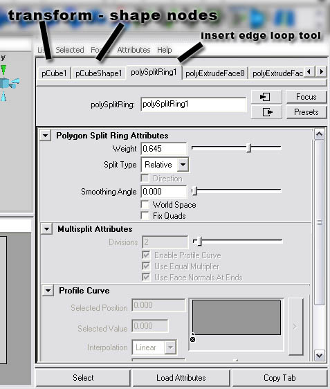 Step five - Look at the weight attribute for the
split ring attributes. This is the percentage that the edge loop will be
created on the edge. Ours is a bit off; we need to be exactly 50%. So
change the value to .5.
Step five - Look at the weight attribute for the
split ring attributes. This is the percentage that the edge loop will be
created on the edge. Ours is a bit off; we need to be exactly 50%. So
change the value to .5.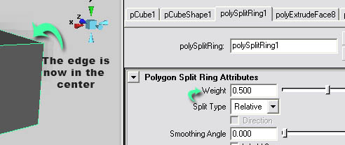 Now that we're done, we can close the attribute editor by clicking on the dotted lines on top of it.
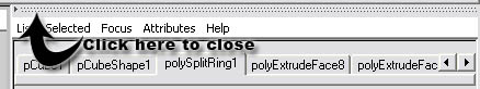 Step six - Go to face mode and select all the faces on the back side.
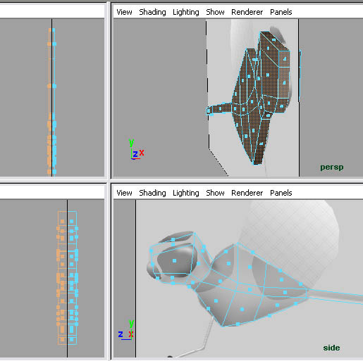 Step seven - Delete them by pressing delete on your keyboard.
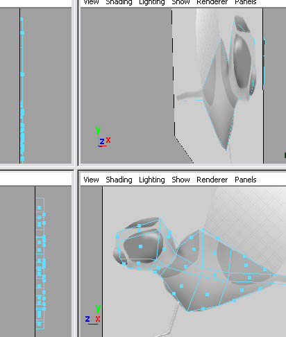 Step eight - Go to object mode, select the object, and go to proxy>subdiv proxy... Click on the box to open the options.
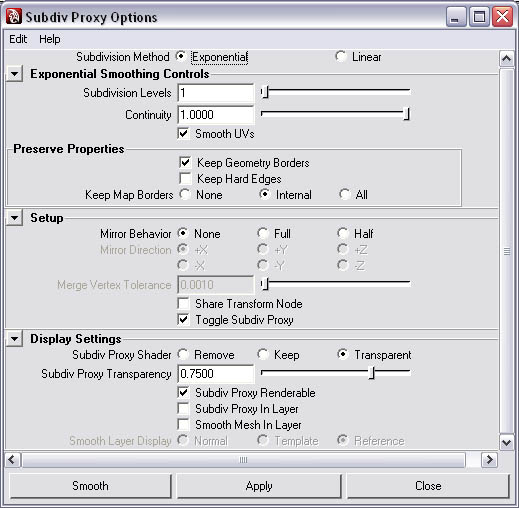 Step nine - We need to set some attributes. First, you want to uncheck keep geometry borders. This will cause the smooth proxy to smooth incorrectly. Second,
set the mirror behavior to half and set the mirror direction to -X. The
-X axis is the side view, so we want to mirror the proxy on the
opposite side (-X). Third, set the subdiv proxy shader to keep. That means the low poly side will remain gray.
Step nine - We need to set some attributes. First, you want to uncheck keep geometry borders. This will cause the smooth proxy to smooth incorrectly. Second,
set the mirror behavior to half and set the mirror direction to -X. The
-X axis is the side view, so we want to mirror the proxy on the
opposite side (-X). Third, set the subdiv proxy shader to keep. That means the low poly side will remain gray.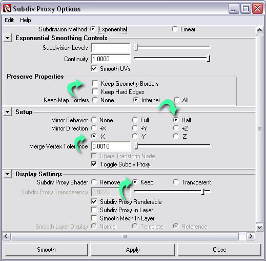 Now click smooth.
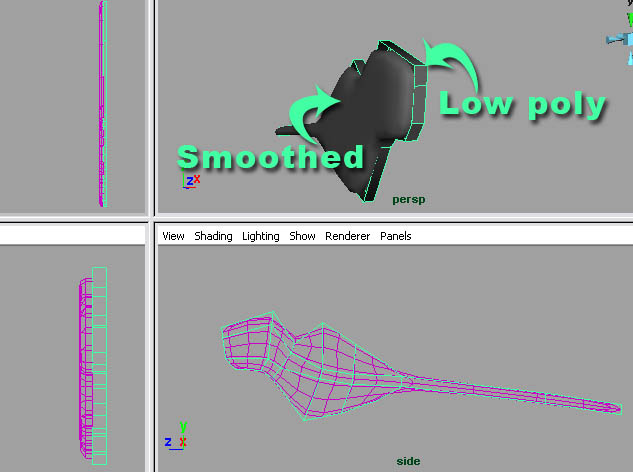 Select the low poly side and try moving a vertex. The smooth proxy side
will mimic and smooth the results. Remember to undo. Also notice how the
proxy side turns purple when you select the low poly side. That's
telling you that these two objects are connected.
Select the low poly side and try moving a vertex. The smooth proxy side
will mimic and smooth the results. Remember to undo. Also notice how the
proxy side turns purple when you select the low poly side. That's
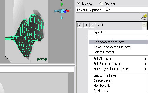
telling you that these two objects are connected.Now we want to restrict our smooth proxy so we can't accidentally select it like our image plane. So select your smooth proxy side, open the layers editor (display>UI elements>channel box/layer editor). Right click on the same layer as the image plane and select add selected objects.
Edge Loops
Edge loops are probably the most important thing to a model. When set up right, the model will smooth correctly, and will be easier to model. If you followed the instructions from part one, the model was designed to have good edge loops. I'm going to try and explain edge loops. I'll use train tracks as a comparison.Like a train, edge loops need ties.
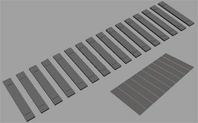 Also like a train, it needs two parallel rails.
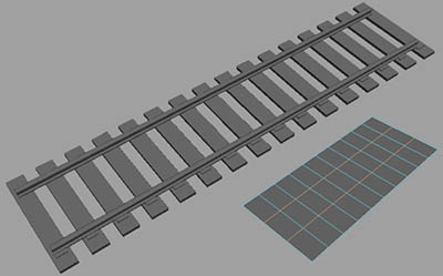 Imagine that the edge loop is following the track. As long as the track doesn't break, it could go on forever.
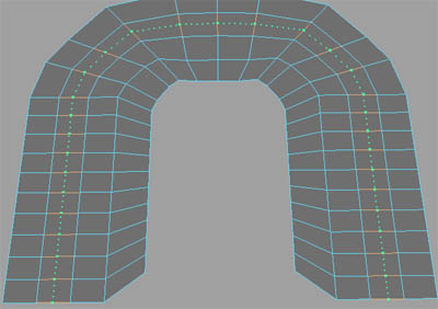 Edge loops can share rails and ties.
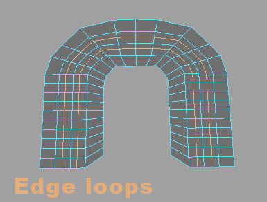 Edge loops can only work on quad geometry.
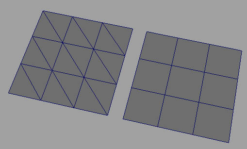 In part one we went into the attributes editor and used the weight
attribute to center an edge loop. Weight is from 0 to 1, and is measured
from rail one to rail two.
In part one we went into the attributes editor and used the weight
attribute to center an edge loop. Weight is from 0 to 1, and is measured
from rail one to rail two.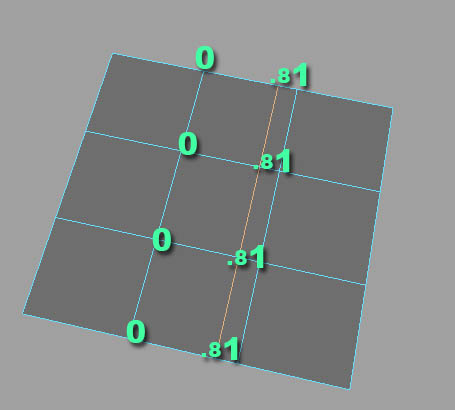
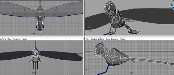
Modeling
Here's a picture of where we left off.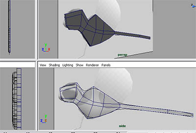 First we're going to need more edges, so we're going to use the "insert edge loop tool" to add them. Go to edit mesh>insert edge loop tool.
We need to add one right in the center of the model. So click on one of
the edges that's transverse to the edges that we want to follow.
First we're going to need more edges, so we're going to use the "insert edge loop tool" to add them. Go to edit mesh>insert edge loop tool.
We need to add one right in the center of the model. So click on one of
the edges that's transverse to the edges that we want to follow.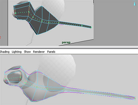 Now go to vertex mode and shape the vertices around the eye.
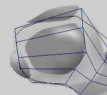 At the moment, the model's almost completely flat. Use the top and front
views to add some width by moving the vertices (notice where the body
is widened).
At the moment, the model's almost completely flat. Use the top and front
views to add some width by moving the vertices (notice where the body
is widened).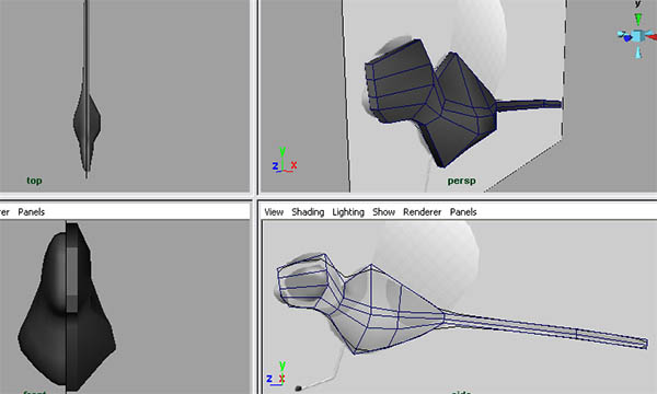 We need another edge loop to round out the underside.
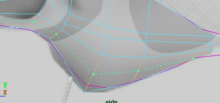 Go to vertex mode and shape the vertices like in the image below.
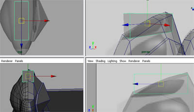
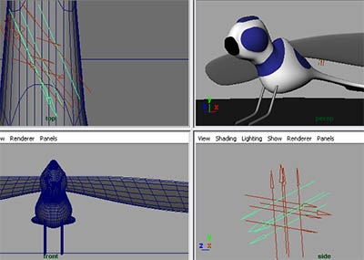
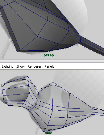 Now we're going back to the eye. We'll add two vertical edge loops and shape it to better match the blueprint.
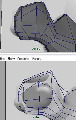 Go to face mode and select the faces over the eye.
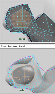 We're going to extrude these faces to form the eye. We'll move it out slightly.
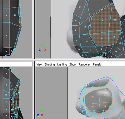 Now select the center vertex in the eye and pull it out.
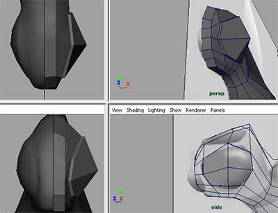 Now I'm going to extrude the nose. First we need to change the base of the nose. Edit the vertices to achieve this.
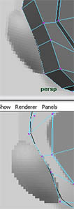 Select the faces on the front of the nose and extrude, just a small bit.
 Now, using the same faces, extrude again and go the rest of the way.
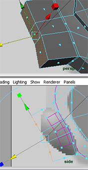 Something went wrong here (sort of). If you look at the model from head
on you can see that there's a face between the proxy and the low poly.
You need to delete this.
Something went wrong here (sort of). If you look at the model from head
on you can see that there's a face between the proxy and the low poly.
You need to delete this.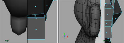 We need to hide the layer. Open the layers editor and click on the V. This will make the layer invisible. Click on the V again to display it later.
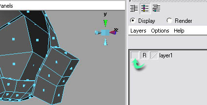 Now you can easily select and delete the faces. Also finish shaping the nose.
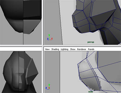 We're going to work on the neck shape now, so add two edge loops and shape them like in the image below.
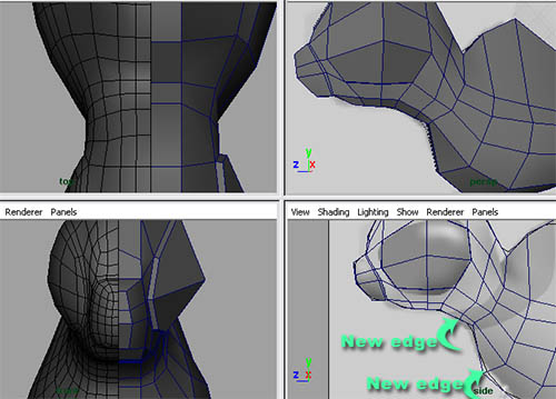 Now for the tail. This dragonfly has somewhat of a spoon tail. First add an edge loop between the two tail edge loops.
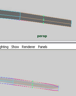 Select the vertices on the side and pull them outwards.
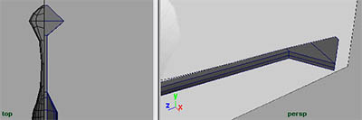 Now for modeling the wings. Unlike the dragonfly that used a box to
start the geometry, we'll be using a different method of creating
geometry. We'll be using the create polygon tool.
Now for modeling the wings. Unlike the dragonfly that used a box to
start the geometry, we'll be using a different method of creating
geometry. We'll be using the create polygon tool.First, go to mesh>create polygon tool. Now, from the top view, click to create each vertex of the new polygon to form the wing.
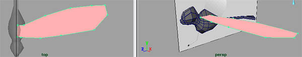 When you're done, press Q. This takes you back to the
default select tool. First let me tell you what's wrong with this
geometry. It's one big face. Most faces are only supposed to have 3 to 4
vertices and edges. This one has a lot more. Here's how we fix it: we
have to convert this geometry into quad geometry. First we have to
triangulate it. Select it and go to mesh>triangulate.
When you're done, press Q. This takes you back to the
default select tool. First let me tell you what's wrong with this
geometry. It's one big face. Most faces are only supposed to have 3 to 4
vertices and edges. This one has a lot more. Here's how we fix it: we
have to convert this geometry into quad geometry. First we have to
triangulate it. Select it and go to mesh>triangulate.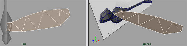 Now, to quadrangulate it, go to mesh>quadrangulate.
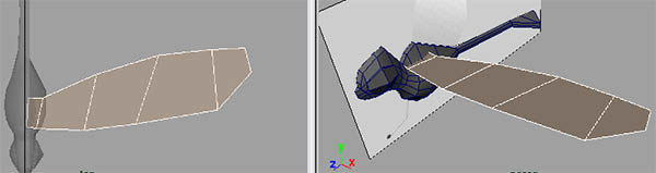 You're probably wondering why we don't go to quadrangulate first and
skip triangulating it. This is one of Maya's odd things: if we were to
quadrangulate it, nothing would happen. But by triangulating it, the
quadrangulate feature can do its job. The reason for this is probably
because it's easier to convert geometry to triangles than to quads, and
it's also easier to convert triangles to quads.
Use the move and rotate tool to position the wing on the body.
You're probably wondering why we don't go to quadrangulate first and
skip triangulating it. This is one of Maya's odd things: if we were to
quadrangulate it, nothing would happen. But by triangulating it, the
quadrangulate feature can do its job. The reason for this is probably
because it's easier to convert geometry to triangles than to quads, and
it's also easier to convert triangles to quads.
Use the move and rotate tool to position the wing on the body.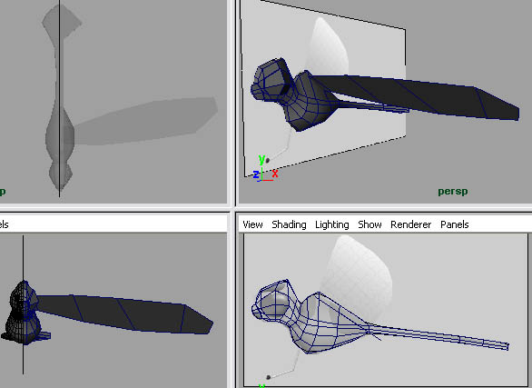 We need to add some thickness to the wing. Select the entire object and
go to edit mesh>extrude. Move the new extruded faces up a bit.
We need to add some thickness to the wing. Select the entire object and
go to edit mesh>extrude. Move the new extruded faces up a bit.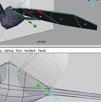 Now for the feet. We're going to extrude the feet from a cylinder along a
curve. First we're going to create the curve. We're going to use the CV
curve tool.
Now for the feet. We're going to extrude the feet from a cylinder along a
curve. First we're going to create the curve. We're going to use the CV
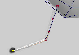
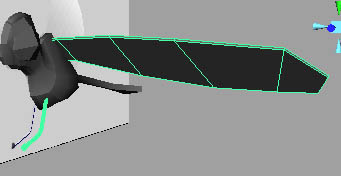
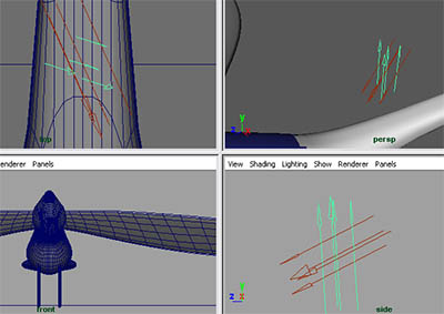
curve tool.Go to create>CV curve tool. To create CV curve points, click on the view port. Continue this until you've created the curve like the image below. The direction that you create the curve in is important; the curve should be created going outwards.
 We need to create a cylinder, so go to create>polygonal
primitives>cylinder. Now move, rotate, and scale it like in the image
below. It has to be in line with the curve.
We need to create a cylinder, so go to create>polygonal
primitives>cylinder. Now move, rotate, and scale it like in the image
below. It has to be in line with the curve.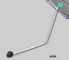 We need to select the faces on the front of the cylinder and the curve
at the same time. If we were to hit F11, the entire scene would be in
face mode, and curves can't be selected in face mode. This is because
they're NURB curves. NURBs don't have faces. So we need to have only our
cylinder go into face mode, and the rest of the scene stay in object
mode. To do this, right click on your model and select face.
We need to select the faces on the front of the cylinder and the curve
at the same time. If we were to hit F11, the entire scene would be in
face mode, and curves can't be selected in face mode. This is because
they're NURB curves. NURBs don't have faces. So we need to have only our
cylinder go into face mode, and the rest of the scene stay in object
mode. To do this, right click on your model and select face.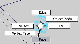 Now select the faces at the end of the cylinder, hold shift on your keyboard, and select the curve.
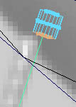 Now go to edit mesh>extrude.
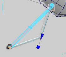 As you can see, there's a problem. It's not completely following the
curve. The answer to this is in the extrude tutorial on this website. Link Here's how to fix this.
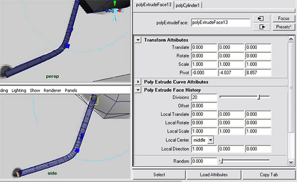
As you can see, there's a problem. It's not completely following the
curve. The answer to this is in the extrude tutorial on this website. Link Here's how to fix this.Select the object and open the attributes editor. Just like edge loops and anything else, we can access extrude settings from past extrudes. Go to the tab polyextrudeface#. Roll down to polyextrudeface history and increase the divisions. 20 to 25 divisions will work.
 Now for the foot. Create a sphere, move and scale it to the position in
the image below. Notice that we squished it a bit horizontally.
Now for the foot. Create a sphere, move and scale it to the position in
the image below. Notice that we squished it a bit horizontally.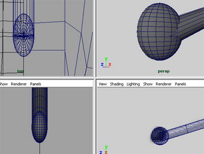 Select the sphere, hold shift, and select the leg and move it like the image below. We'll mirror the other leg later.
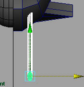 Now for the last piece. This is the little helmet on its head. This will
be a separate object because this will be assigned with a blinking,
glowing material.
Now for the last piece. This is the little helmet on its head. This will
be a separate object because this will be assigned with a blinking,
glowing material.Make a cube. Scale and position it like in the image below.
 Add two edge loops and shape it like the image below.
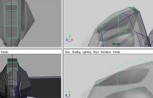 Go to object mode and select it and go to mesh>smooth.
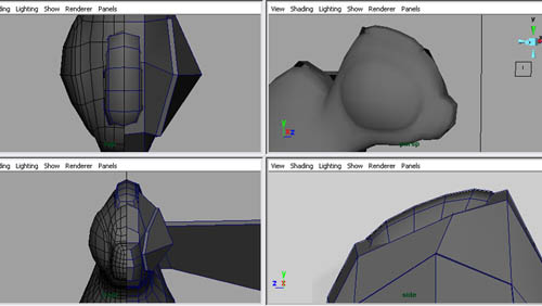 Now that we're done modeling all the components, we're going to mirror the wings and the leg to the opposite side of the model.
First select the wing and the leg all together (use shift). We're going to group them and duplicate the group to the opposite side. To group them, go to edit>group.
 Now go to edit>duplicate special... Open the options.
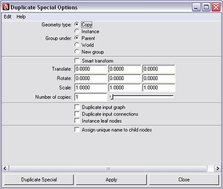 We want to set the first scale option to -1. This will mirror it to the
other side. To learn more about duplicate special, read this tutorial.Link
We want to set the first scale option to -1. This will mirror it to the
other side. To learn more about duplicate special, read this tutorial.Link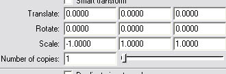 Now click duplicate special.
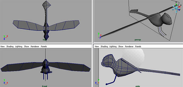
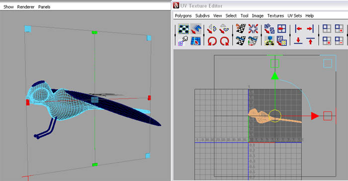
UV Mapping
UV mapping is the process of converting a 3D model into a 2D plane that can be textured in a 2D editing program to add color, bumpmap, etc. This is done through UVs. UVs are similar to vertices, but, unlike vertices, they work in 2D space using the UV editor in Maya. The images below describe the UV mapping workflow.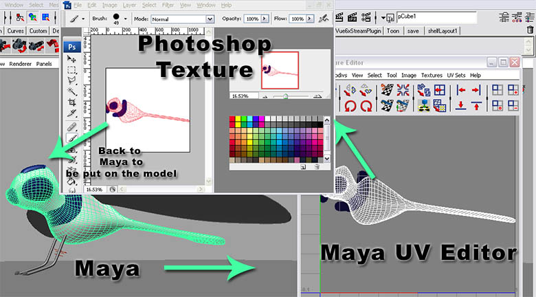
Finishing The Model
Here's where we left off: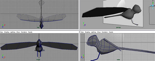 First we're going to need to delete the image plane. So, on the side
view port camera, go to view>image plane>image plane
attributes>imageplane1.
First we're going to need to delete the image plane. So, on the side
view port camera, go to view>image plane>image plane
attributes>imageplane1.Go to edit>delete.
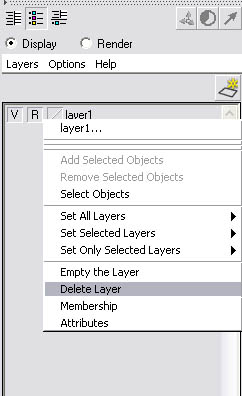
Now we need to delete the layer (this layer also contains a smooth proxy), so open the layers editor and right click on the layer and select delete layer; this will remove the reference from the smooth proxy, enabling us to select it now.
 I have a tutorial covering removing smooth proxys; you can read it here. I've shortened the steps here.
Step one - Select the smooth side and delete it.
Step two - Select your model and go to mesh>mirror geometry... Open the options and set the mirror direction to -X (same as our smooth proxy), check merge with the original and check merge vertices.
 Step three - Some of the model's vertices will be "crimped" together.
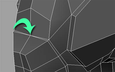 To fix this, select your model and open the attributes editor. Go to
polyMirror# and set the merge threshold to something like 0.008 or
0.010. This will prevent that from happening but still merge the two
halves together.
To fix this, select your model and open the attributes editor. Go to
polyMirror# and set the merge threshold to something like 0.008 or
0.010. This will prevent that from happening but still merge the two
halves together.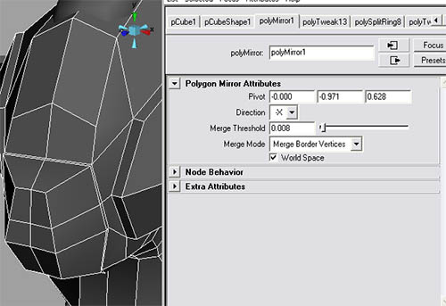 On to smoothing. Select your wings, body, and head piece and go to mesh>smooth... Open the options by clicking on the box.
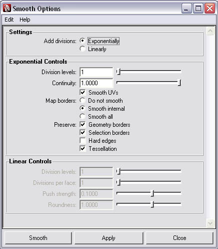 We want to smooth more times than when we were smoothing it previously.
So set the divisions to 2. We don't want to preserve any of the
geometry, so uncheck the preserve options.
We want to smooth more times than when we were smoothing it previously.
So set the divisions to 2. We don't want to preserve any of the
geometry, so uncheck the preserve options.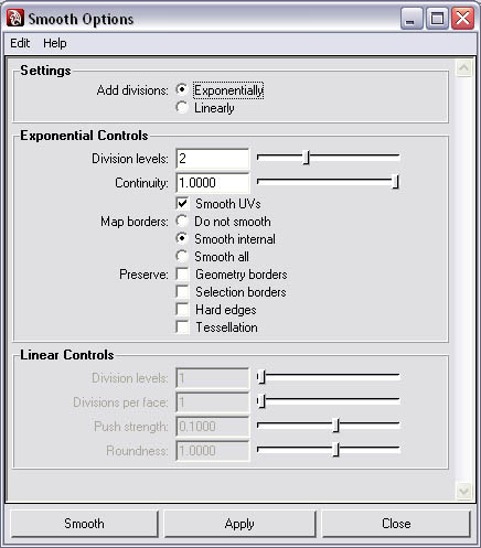 Now click smooth.
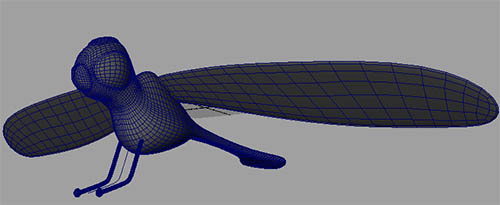 Now to clean up the scene. If you remember in part one we were talking
about history, all that history is still there; this will cause problems
later on. Since we no longer need to edit the history, we should delete
it. So go to edit>delete all by type>history.
This deletes all the history in the scene. If you wanted to delete the
history for only the selected objects, you would go to edit>delete by
type>history.
Now to clean up the scene. If you remember in part one we were talking
about history, all that history is still there; this will cause problems
later on. Since we no longer need to edit the history, we should delete
it. So go to edit>delete all by type>history.
This deletes all the history in the scene. If you wanted to delete the
history for only the selected objects, you would go to edit>delete by
type>history.Delete the curve we used to create the leg. If we didn't delete history before we deleted the curve, it would also delete the left leg. This is because there's a connection between the curve and the extrusion history on that leg. The reason the other side wouldn't be deleted is because when you duplicate the leg, the leg's history is deleted.
UV Mapping
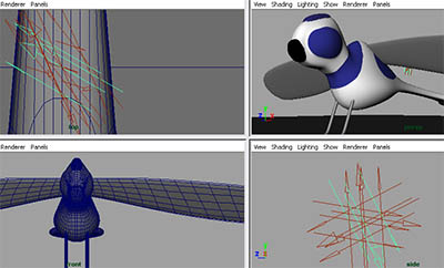
Due to the simplicity of our model, we're not going to go into a full-fledged UV map tutorial, but we'll cover the basics.First we need to open the UV editor. Go to window>UV editor.
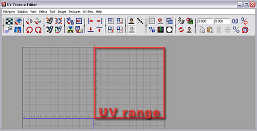 Now select the model.
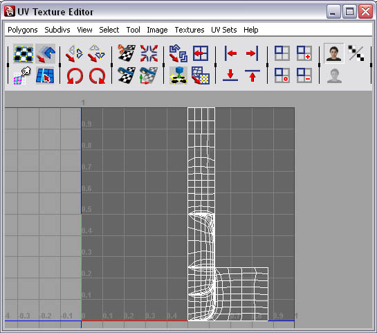 All those lines that are in the UV editor are the object's UVs in their
current position. As you can see it would be pretty hard to paint on
because we have no clue where these UVs connect to. This is where UV
mapping comes in.
All those lines that are in the UV editor are the object's UVs in their
current position. As you can see it would be pretty hard to paint on
because we have no clue where these UVs connect to. This is where UV
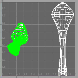
mapping comes in.Step one - With the model selected, go to create UVs>planar mapping... Open the options.
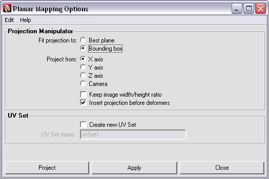 Step two - We're going to project a 2D plane on the X
axis (side). So check project from X axis. Also we want to check "keep
image width and height ratio". The reason we checked this is so it won't
get stretched out to fit the maximum UV range.
Step two - We're going to project a 2D plane on the X
axis (side). So check project from X axis. Also we want to check "keep
image width and height ratio". The reason we checked this is so it won't
get stretched out to fit the maximum UV range.Click project.
 Step three - Now the UV editor is starting to make
some sense. You can tell where the UVs are on the model. When we paint
our texture (color), we'll be painting on these UVs.
Step three - Now the UV editor is starting to make
some sense. You can tell where the UVs are on the model. When we paint
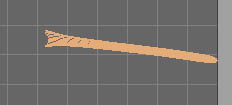
our texture (color), we'll be painting on these UVs.Step four - Notice how we can't paint on the flat part on top of the tail, mainly because we can't see it. We'll need to fix this by doing a planar map that's looking down (Y axis) so we can see the tail. Right click on the UVs in the UV editor and select face. Now select all the faces on the tail. Note: Make a rectangle over them to select them; it's faster.
 Step five - Go to create UVs>planar mapping... Open the options. Set the "project from" to Y and click project.
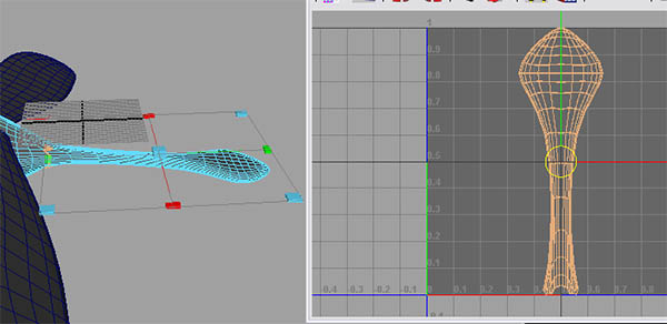 Step six - Press F12 on your keyboard. Now you can select the UVs.
Step seven - We want to use as much of the UV space as possible. So we're going to move some of the UVs around. First we want to move the tail to the right side. Select one UV point inside the tail's UV's (this is called a UV shell).
 Step eight - Go to select>convert seleection>to UV shell. This selects all the tail's UVs.
 Step nine - Press W to activate the move tool and move the UVs to the right side of the UV range.
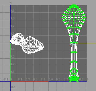 Now for the body. We're going to rotate it and make it larger.
Step one - Deselect the tail's UVs by clicking in any empty space in the UV editor. Now select the UV point inside the body's shell.
Step two - Go to select>convert selection>to UV shell. Now, in the UV editor, go to polygons>rotate... Open the options. Set it to 90 degrees and click rotate UVs.
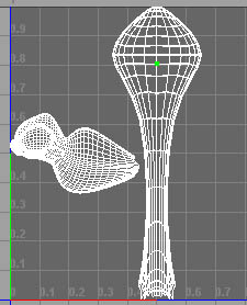
 Step three - Press R to activate the scale tool and scale it up to the maximum UV range. You may need to move it a bit closer to the tail.
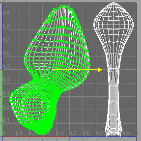 Step four - Select all UVs (just make a big
rectangle over all the UVs) and go to polygons>rotate... and open the
options. Set the rotation ange to -90. Click rotate.
Step four - Select all UVs (just make a big
rectangle over all the UVs) and go to polygons>rotate... and open the
options. Set the rotation ange to -90. Click rotate.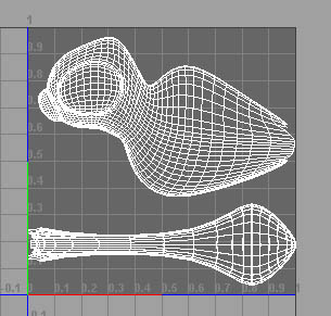
Texturing
Use the image below that visually describes the texturing process.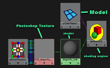 A file with the texture loaded in it is connected to the color channel
of a shader. The shader is connected to a shading engine, and the model
is connected to the shading engine.
A file with the texture loaded in it is connected to the color channel
of a shader. The shader is connected to a shading engine, and the model
is connected to the shading engine.Texturing The Dragonfly
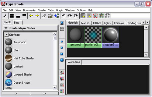
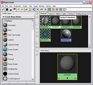
First we're going to create a bitmap Adobe Photoshop file that will contain the texture for the dragonfly.We need to open the hypershade. The hypershade is where you do all your material editing in Maya.
To open the hypershade, go to window>rendering editors>hypershade.
 I have a tutorial on this site covering everything in the hypershade.Link
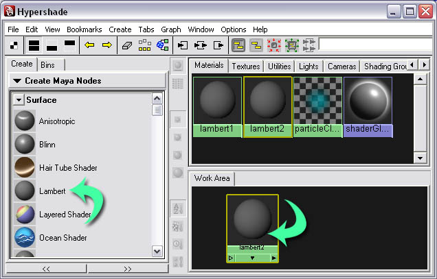
On the create Maya node side, click on the Lambert shader. The model has already been assigned with a shader (the default shader is Lambert1). The default shader is assigned to every model in the scene. This is a problem, considering our dragonfly's texture is not the same texture for the entire scene. So that's why we created a new Lambert shader specifically for the dragonfly.
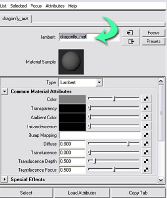
 Select the new shader and open the attributes editor.
We want to change the name of the shader to dragonfly_mat.
 Select your model in the view port and right click and hold on the shader and click assign material to selected.
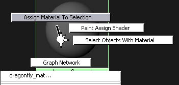 This connects the model to the Lambert's shader engine. We don't need to
create our file node that will connect to our color because Maya has an
automated feature to do this for us.
This connects the model to the Lambert's shader engine. We don't need to
create our file node that will connect to our color because Maya has an
automated feature to do this for us.Select your model and go to texturing>create PSD network...
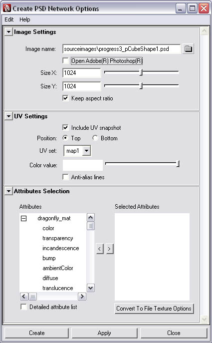 First we need to set the size of our texture. Since this is a bitmap
image we'll be creating, the larger the image, the more pixels we'll
have to paint on, in other words, adding more detail to the texture.
Since this is a basic texture, we'll only need a1024 by 1024 image.
First we need to set the size of our texture. Since this is a bitmap
image we'll be creating, the larger the image, the more pixels we'll
have to paint on, in other words, adding more detail to the texture.
Since this is a basic texture, we'll only need a1024 by 1024 image.Make sure that "include UV snapshot" is checked and its position is set to top. The rest you can leave to their default settings.
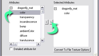
Now for the attributes selection. Our dragonfly_mat is already loaded here. We want to create a color texture map, so click color, then click on the arrow that loads it into the selected attributes.
 Now roll back up to the top and check open Adobe(R) Photoshop(R). That
way, when the texture is created, it will load it into Adobe Photoshop
for us.
Now roll back up to the top and check open Adobe(R) Photoshop(R). That
way, when the texture is created, it will load it into Adobe Photoshop
for us.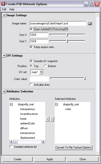 Now click create.
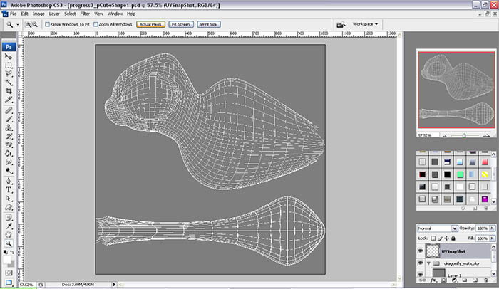
Painting In Adobe Photoshop
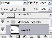
Now that we have Adobe Photoshop open, it's time to start texturing.We'll be painting our texture on layer 1 inside the group dragonfly_mat.color. We have to paint only on layers inside the group dragonfly_mat.color. This is because when Maya sources the texture, it connects to that group in the Adobe Photoshop file. Anything outside the group will be ignored.
 This tutorial assumes that you have a basic knowledge of Adobe
Photoshop. You can texture this any way you want to, but to get the same
result that I did, first fill the background in with white.
This tutorial assumes that you have a basic knowledge of Adobe
Photoshop. You can texture this any way you want to, but to get the same
result that I did, first fill the background in with white.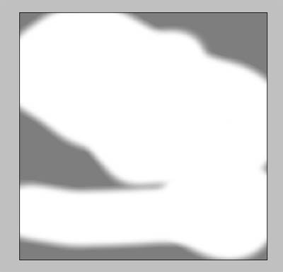 Now fill his eyes in with purple.
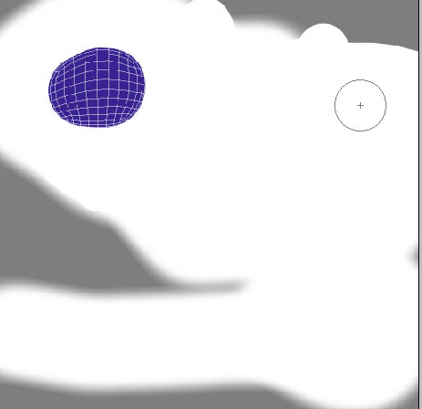 Add more purple on the body.
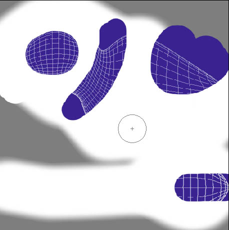 Fill the nose in with black.
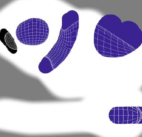 When you're done texturing, save.
Back To Maya
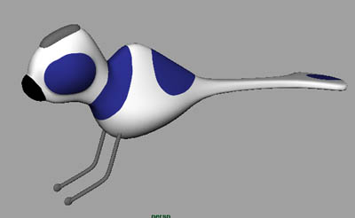
After you've saved the Adobe Photoshop file, go back to the Maya window and select the model and go to texture>update PSD networks.As you tweak your texture, you're probably going to want to see the texture in the view port. So go to shaded display mode and, on the view port menu, go to shading>hardware texturing.
 Now it's time to make materials for other objects. First we'll create the wings' shader.
Create another Lambert.
 Select the new Lambert shader and open the attributes editor.
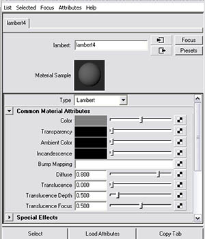 Click on the color swatch; the color chooser will come up. Set the color to white.
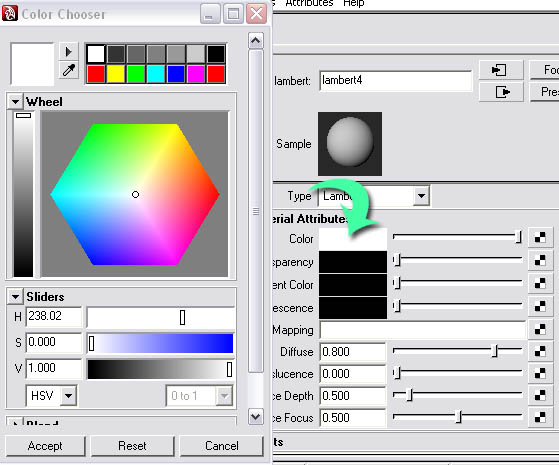 Now select the wings and right click on the shader and assign the shader to the object.
Now for the glowing headpiece.
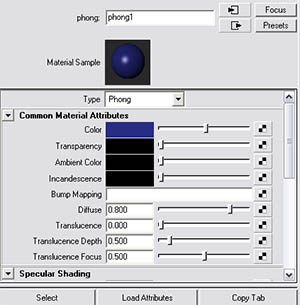
Create a phong shader. This shader has a shine somewhat similar to plastic. Select it and open the attributes editor. Change its color to purple, the same color you used on the body of the dragonfly.
 To add the glow effect, roll down to special effects and set the glow intensity to.4.
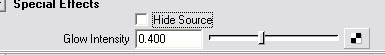 Now select the headpiece and assign the shader to the headpiece.
Now create a blinn shader (a blinn shader is similar to metal). Assign the shader to the legs of the model.
Last, create a Lambert shader, set the color to dark gray, and assign it to the feet.
 Now we're ready for rendering.
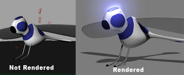
Rendering uses lights and a rendering software to convert your 3D model into a 2D rendered image of your model. The rendered image of your model looks better than what your model would look like in the view port.
 First let's create lights for our rendering. First you may want to read this tutorial on lights. Link
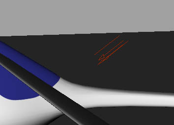
Go to create>lights>directional lights. Select it and rotate it like in the image below. Directional lights, unlike other lights, aren't affected by their position in the scene, only the direction it's pointing.
 We need to change the intensity of the light, so select the light and open the attributes editor.
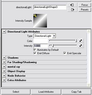 Set the intensity to 1.405.
Create another light and rotate this one so it's coming up from underneath.
 Set its intensity to 0.496.
Create another light and set this one coming in on an angle similar to the angle of the camera when you render your scene.
 Set this light's intensity to 0.248.
Create another light and angle this one so that it comes in from a general downwards direction. Set it's intensity to 0.826.
 Now do a quick test rendering. To render a scene, go to render>render current frame.
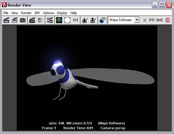 Now time to fix the background. First we want to create a polygonal
plane to act as the floor for the dragonfly to sit on. Go to
create>polygonal primitives>plane. Position it under the dragonfly
and scale it extremely large.
Now time to fix the background. First we want to create a polygonal
plane to act as the floor for the dragonfly to sit on. Go to
create>polygonal primitives>plane. Position it under the dragonfly
and scale it extremely large.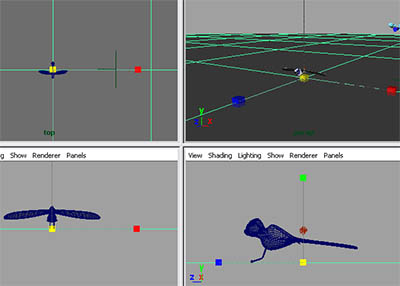 Now we need to change the background color to gray instead of black.
On the view port menu set go to view>select camera. Open the attributes editor.
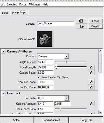 Roll down to environment. Set the background color to roughly 50% gray.
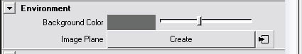 Now render.
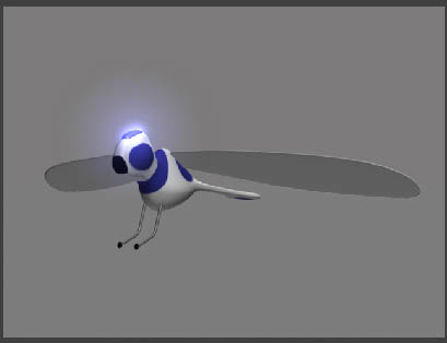 It needs shadows. Select the light coming in from the general angle and
open the attributes editor. Roll down to shadows, depth map shadows.
Check "use depth map shadows". Increase the resolution to 2000.I have a
Tutorial on shadows here.LINK
It needs shadows. Select the light coming in from the general angle and
open the attributes editor. Roll down to shadows, depth map shadows.
Check "use depth map shadows". Increase the resolution to 2000.I have a
Tutorial on shadows here.LINK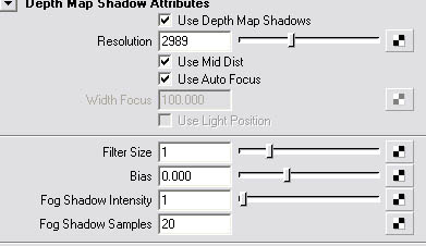 Take a test render.
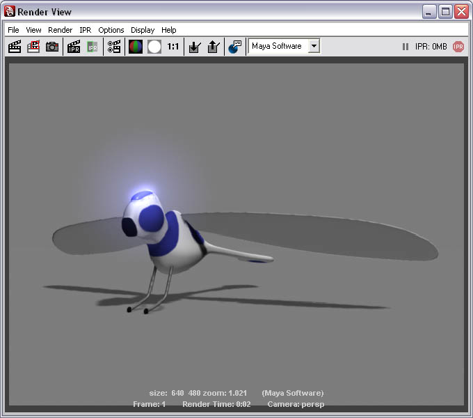 Now we're done.
)